From Holdwell—your trusted source for mower pto switch, lawn mower pto switch, and OEM‑grade replacements. This guide gives you ready‑to‑use wiring diagrams, terminal functions, wire colors, safety circuits, and brand‑specific notes for Delta, Bobcat, John Deere.
Basic PTO switch wiring logic (all mowers)
A PTO switch controls two core jobs:
-
Engage/disengage the electric PTO clutch (blade power)
-
Integrate safety interlocks (seat, reverse, brake, starter inhibit)
Power path:
Battery → Ignition → PTO Switch → PTO Clutch/Relay → Safety Modules → Ground
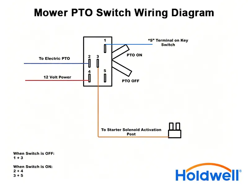
5 Pin mower PTO switch wiring diagram (most common)
Standard terminal labeling: 12V IN | PTO Clutch | Ground | Safety Interlock | Starter Interlock
|
Terminal |
Function |
Common Wire Color |
Connection |
|
Pin 1 |
12V Power In |
Red |
Ignition switch (12V when key ON) |
|
Pin 2 |
PTO Clutch Output |
Green/White |
PTO clutch coil or PTO relay |
|
Pin 3 |
Ground |
Black |
Chassis ground |
|
Pin 4 |
Safety Interlock (Seat/Reverse) |
Yellow |
Seat switch / RCM module |
|
Pin 5 |
Starter Interlock |
Orange |
Starter solenoid (prevents start with PTO ON) |
Wiring steps:
-
Disconnect battery negative
-
Red → Pin1 (12V IN)
-
Green/White → Pin2 (Clutch)
-
Black → Pin3 (Ground)
-
Yellow → Pin4 (Safety)
-
Orange → Pin5 (Starter inhibit)
-
Test PTO engage/disengage & safety interlocks
8 Pin PTO switch wiring diagram
Used on Delta, Bobcat, Cub Cadet, commercial zero‑turns.
|
Pin |
Function |
Typical Wire |
Purpose |
|
1 |
12V Battery + |
Red |
Constant power |
|
2 |
Ignition 12V |
Pink |
Key‑switched power |
|
3 |
PTO Clutch Output |
Green |
To clutch coil |
|
4 |
PTO Relay Latch |
White/Black |
Self‑hold relay circuit |
|
5 |
Seat Safety |
Yellow/Black |
Seat switch interlock |
|
6 |
Reverse Safety |
Blue |
Reverse cut‑off |
|
7 |
Brake Interlock |
Orange |
Brake/PTO starter lock |
|
8 |
Ground |
Brown |
Chassis ground |
Brand‑specific PTO switch wiring from Holdwell fitments
Delta PTO switch wiring
-
Series 6201 / 6204 use 5‑pin & 8‑pin
-
Sealed IP67; color code matches above
-
Direct plug‑and‑play for most tractors & zero‑turns
Bobcat PTO switch / Bobcat mower PTO switch
-
Mostly 8‑pin heavy‑duty
-
Vibration‑resistant contacts
-
Match OEM part numbers for correct pinout
John Deere PTO switch wiring
-
Most models: 5‑pin
-
Common part numbers: AM147972, AM101562, AM133837
-
Holdwell john deere pto switch replacement plugs straight into factory harness
-
Safety circuits fully restored
Safety wiring rules (critical!)
-
Never bypass safety interlocks (seat, reverse, brake)
-
Always use inline 10–15A fuse for PTO circuit
-
Bad grounding = intermittent PTO & clutch burnout
-
Loose connections cause heat, melted plugs, switch failure
How to test your wiring?
-
Key ON, PTO OFF: Pin1 = 12V; Pin2 = 0V
-
Key ON, PTO ON: Pin1 = 12V; Pin2 = 12V (clutch activates)
-
If no 12V at Pin2: bad switch, broken wire, or blown fuse
-
If clutch chatters: weak ground or failing switch
Why use Holdwell PTO switches?
-
Exact pinout & wire match for mower pto switch
-
OEM‑grade terminals prevent melting & shorts
-
Protects your PTO clutch from damage
-
Plug‑and‑play for Delta, Bobcat, John Deere, Cub Cadet
Conclusion
This mower pto switch wiring diagram works for most residential & commercial mowers. Always cross‑check your model’s schematic. For a perfect‑fit replacement with correct wiring harness, choose Holdwell.
Need a custom diagram for your exact model? Just tell me your machine brand & model—I’ll send a tailored pinout.